
IR 102 Remote Control Kit • Installation and Operation
Installation and Operation, cont’d
1-10
IR 102 Remote Control Kit • Installation and Operation
1-11
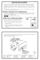
Features and Connections
IR 102 Rx UNIVERSAL IR REMOTE RECEIVER
RS-232/
CONTACT
OUT
RS-232
Tx Rx12345+5
+12V
6
CONTROL OUT
IR IN
CONTACT
MOD
DEMOD
POWER
12V
.5A MAX
RS-232
IN
4
1
2
3
6
5
IR 102 Rx remote receiver front and rear panels
a
Power LED — When lit, this LED indicates power is applied.
The LED blinks during communication activity.
b
Power connector — Plug the external 12 V power supply
into this 2-pole captive screw connector. The power supply is
included with the unit. The fi gure below shows how to wire the
connector.
C
When connecting the power supply, voltage polarity
is extremely important. Applying power with
incorrect voltage polarity could damage the power
supply and the remote receiver. Identify the power
cord negative lead by the ridges on the side of the
cord.
Power Supply
Output Cord
SECTION A–A
Ridges
Smooth
AA
Ridges
Power connector wiring
N
Do not tin the stripped power supply leads before
installing the captive screw connector. Tinned wires are
not as secure in the captive screw connectors and could
pull out.
5. If desired, remove the back panel of the PMK 350 and
mount an additional IR 102 Rx or other device(s) at the
back of the bracket, as described in step 3 on the previous
page.
6. Place the PMK 350 mounting tray around the projector
ceiling mounting pole. (See the illustration on page 1-9.)
7. Assemble the U-bolt and the following parts in the order
they are listed below:
a. Pass the legs of the U-bolt through the slotted holes on
the back of the mount plate fl ange.
b. Place the U-bolt legs around the ceiling pole.
c. Pass the U-bolt legs through the round holes in the
contoured base.
N
Place the contoured base against the pole and opposite
the mount plate fl ange. The pole should fi t snugly into
the depression in the center of the contoured base.
d. Pass the U-bolt legs through the round holes in the
L-shaped bracket.
8. Align the two round holes in the bottom of the L bracket
with the two slotted holes in the base of the PMK 350,
on either side of the opening for the pole; and attach the
L-shaped bracket to the base by inserting the two provided
6-32 x 5/16" screws through the aligned slots. Tighten
the screws slightly; you should still be able to slide the
L-shaped bracket to adjust it as needed.
Connecting the IR 102 Rx to a Switcher
1. Power down the switcher.
2. Connect the IR 102 Rx to the switcher
via the RS-232 or contact closure ports,
available on both 9-pin and captive screw
connectors.
3. Position the IR sensor at the best location
for the IR 102 handheld remote control.
4. Connect the IR Sensor to the IR In
connector on the remote receiver.
5. Connect the external power supply to
the remote receiver, then plug one end
of a standard IEC power cord into the
power supply and the other end into a
100-240 VAC, 50/60 Hz power source.
6. Power up the switcher.
1TxRx23456
RS-232
CONTROL OUT
CONTACT
Pin - 1
Pin - 2
Pin - 3
Pin - 4
Pin - 5
Pin - 6
Gnd
Tx
Rx
Gnd
Contact Closure
RS-232


 England
  Deutschland
  France
  Italia
  Polska
  United Kingdom
  Россия
  Nederland
  España
  Magyarország
  Sverige
  România
  Portugal
  Colombia
  Suomi
Suomi  New Zealand
  Česká republika
  Türkiye
  Danmark
  日本
日本