
1
PowerCage 1600 Enclosure • Setup Guide
The Extron
®
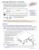
PowerCage 1600 is a rack-mountable, 16-slot enclosure with vents, fans, an
integrated power supply, and optional redundant power supply that supports PowerCage
transmitter and receiver boards. PowerCage fiber optic (FOX) boards and PowerCage
twisted pair (MTP) boards are mounted within the PowerCage Enclosure and can be used
in any combination. Each optional board operates independently of the others, creating an
integrated system of individual transmitters and receivers, not a matrixed system.
5A MAX.
100-240V 50/60Hz
PowerCage 1600
Power Supply
PowerCage 1600
Power Supply
N15 778
I.T.E.
1T23
Slot Numbers
Power
Supply
1
Power
Supply
2
16 123456789101112131415
Main
Power
Supply
(standard)
Slot for
Redundant
Power Supply
(optional)
Slots for Transmitter and Receiver Boards
(up to 16 single-slot or 8 double-slot optional boards)
Power
Connector
NOTES: The front panel
board status LED
numbers correspond to
the slot numbers.
Cover all empty board
slots; DO NOT leave them
open. Securely fasten the
retaining screws for
boards and blank panels.
Heed the following safety information when installing or servicing the PowerCage system:
CAUTION: The PowerCage uses double pole/neutral fusing. Power must be disconnected before servicing internal
components. Do not leave empty board slots open or uncovered while the unit is powered on.
Installation
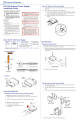
Step 1: Install the redundant power supply and transmitter and receiver boards.
Refer to the model-specific guide for each PowerCage transmitter and receiver board you are installing. Some boards have
switches that must be set before installation. The guides describe the features of each board and how to set up and cable it.
NOTES: The boards are hot-swappable; they can be installed or removed without turning off or disconnecting the
power to the PowerCage Enclosure. Use ESD precautions when installing a board to avoid damaging it. Keep
the board in the anti-static bag until it is needed. Use proper grounding techniques during installation.
a. Remove as many blank plates or previously installed boards from the
rear of the PowerCage Enclosure as necessary for the number of
new boards to be installed. Save the screws for use in step 3.
b. Hold the board with the signal connectors towards
you and the LED at the top, and align the top and
bottom grooves of the board with the slide
posts in the selected enclosure slot. See
the figure at right.
c. Carefully slide the board into the slot,
aligning the two tabs on the lower
front end of the board with the
matching ports in the enclosure.
Push the board firmly into place.
Tighten the screws to secure the board
in place.
d. Repeat steps b and c for all boards
needing installation.
NOTE: Use a tool to fully tighten the screws after
initial installation and subsequent removal
and replacement of the boards.
e. If desired, connect power to the enclosure and verify that the fans, boards, and LEDs power up correctly; then
disconnect power.
MONO
AUDIO OUTPUT
1 2
SHARP
GAIN
Y/VID
C
INPUT
PowerCage
MTP R AV
Tx Rx
HD/SDI INPUT HD/SDI OUTPUTS
MODE
PowerCage
FOX 3G HD-SDI
1 2
REMOTE
RS-232
RS-232
OVER FIBER
Tx Rx
Tx
ALARM
Rx
OUTPUT
RGB
PowerCage
FOX 4G RX RGB
Tx Rx
L R
AUDIO
5A MAX.
100-240V 50/60Hz
N157 78
C
US
LIST ED
1T23
I.T.E.
Screws
(2 per
board)
1 2
REMOTE
RS-232
RS-232
OVER FIBER
Tx Rx
Tx
ALARM
Rx
OUTPUT
RGB
PowerCage
FOX 4G RX RGB
Tx Rx
L R
AUDIO
Align board and
slide into slot.
Figure 1. Inserting Boards into the PowerCage Enclosure
(Continued on page 2)
Contents
Installation ..............................................................................1
Step 1: Install the redundant power supply and transmitter
and receiver boards...........................................................1
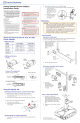
Step 2: Mount the enclosure to an equipment rack. ...........2
Step 3: Connect A/V and control cables. ............................2
Step 4: Connect power and test the system. ......................2
Contact Information ...............................................................2


 England
  Deutschland
  France
  Italia
  Polska
  United Kingdom
  Россия
  Nederland
  España
  Magyarország
  Sverige
  România
  Portugal
  Colombia
  Suomi
Suomi  New Zealand
  Česká republika
  Türkiye
  Danmark
  日本
日本